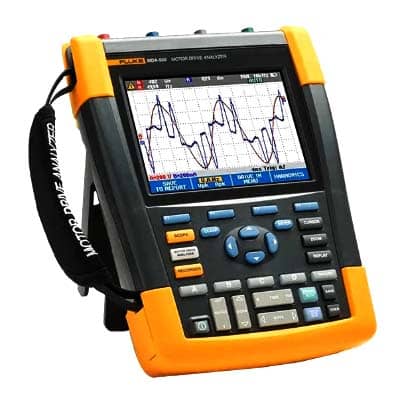
Fluke MDA-550 Series III Motor Drive Analyzer
Precision motor drive analysis for dependable industrial performance.

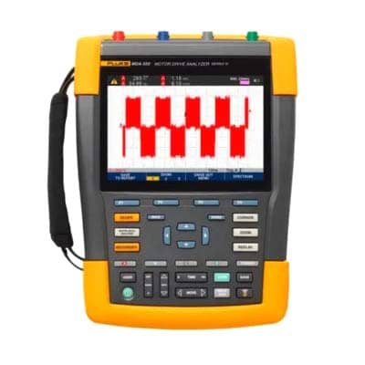
Fluke MDA-550 Series III is a professional motor drive analyzer designed to simplify drive system diagnostics and improve maintenance efficiency, making Fluke MDA-550 Series III Motor Drive Analyzer Price in Bangladesh a frequently searched term among engineers, maintenance professionals, and industrial buyers seeking a reliable testing solution. This advanced analyzer helps evaluate motor drive performance, identify electrical issues, and support efficient troubleshooting to ensure the smooth operation of industrial equipment.
The Fluke MDA-550 motor drive analyzers Series III provides comprehensive diagnostic capabilities for variable frequency drives and motor systems. It enables professionals to analyze electrical performance, detect abnormal operating conditions, and identify potential faults before they affect production. Accurate diagnostics help improve equipment reliability while reducing maintenance time and operational disruptions.
Designed with productivity in mind, the analyzer features an intuitive interface and guided measurement functions that simplify complex testing procedures. The clear display and easy navigation allow technicians to perform inspections efficiently, making it suitable for both experienced engineers and maintenance personnel working in demanding industrial environments.
The Fluke MDA-550 Series III is widely used in manufacturing plants, automation systems, processing facilities, utility services, commercial buildings, and maintenance departments. It supports professionals in monitoring motor drive performance, evaluating electrical systems, and maintaining reliable operation of critical machinery. Its versatility makes it an essential tool for a wide range of industrial applications.
Built for challenging field conditions, the Fluke MDA-550 Series III features a rugged and durable design that delivers dependable performance during regular use. Its robust construction helps maintain accurate measurements while withstanding demanding industrial environments. This durability ensures long term reliability for routine inspections and advanced troubleshooting tasks.
The analyzer helps maintenance teams identify developing motor drive issues before they result in unexpected equipment failures. Early fault detection supports preventive maintenance strategies, reduces unplanned downtime, and extends the service life of valuable equipment. Reliable analysis also contributes to improved operational efficiency and optimized maintenance planning.
Professionals choose the Fluke MDA-550 Series III because of its accurate diagnostic capability, user friendly operation, durable construction, and dependable performance. Whether used for preventive maintenance, motor drive troubleshooting, or electrical system evaluation, it delivers reliable results that support informed maintenance decisions. Buyers searching for Fluke MDA-550 Series III Motor Drive Analyzer Price in Bangladesh can confidently evaluate this analyzer based on its functionality, durability, and long term value.
| Measurement and Analysis Combinations | |||||
| Test point | Sub group | Reading 1 | Reading 2 | Reading 3 | Reading 4 |
| Motor drive input | |||||
| Voltage and current | |||||
| Phase-phase | V-A-Hz | V ac+dc | A ac+dc | Hz | |
| V peak | V peak max | V peak min | V pk-to-pk | Crest factor | |
| A peak | A peak max | A peak min | A pk-to-pk | Crest factor | |
| Phase-ground | V-A-Hz | V ac+dc | A ac+dc | Hz | |
| V peak | V peak max | V peak min | V pk-to-pk | Crest factor | |
| A peak | A peak max | A peak min | A pk-to-pk | Crest factor | |
| Voltage unbalance | Unbalance | V ac+dc | V ac+dc | V ac+dc | Unbalance |
| Peak | V pk-to-pk | V pk-to-pk | V pk-to-pk | ||
| Current unbalance | Unbalance | A ac+dc | A ac+dc | A ac+dc | Unbalance |
| Peak | A pk-to-pk | A pk-to-pk | A pk-to-pk | ||
| Motor drive DC bus | |||||
| DC | V dc | V pk-to-pk | V peak max | ||
| Ripple | V ac | V pk-to-pk | Hz | ||
| Motor drive output | |||||
| Voltage and current (filtered) | V-A-Hz | V PWM | A ac+dc | Hz | V/Hz |
| V peak | V peak max | V peak min | V pk-to-pk | Crest factor | |
| A peak | A peak max | A peak min | A pk-to-pk | Crest factor | |
| Voltage unbalance | Unbalance | V PWM | V PWM | V PWM | Unbalance |
| Peak | V pk-to-pk | V pk-to-pk | V pk-to-pk | ||
| Current unbalance | Unbalance | A ac+dc | A ac+dc | A ac+dc | Unbalance |
| Peak | A pk-to-pk | A pk-to-pk | A pk-to-pk | ||
| Voltage modulation | |||||
| Phase-phase | Zoom 1 | V PWM | V pk-to-pk | Hz | V/Hz |
| Zoom 2 | V peak max | V peak min | Delta V | ||
| Zoom 3 peak | V peak max | Delta V/s | Risetime peak | Overshoot | |
| Zoom 3 level | Delta V | Delta V/s | Risetime level | Overshoot | |
| Phase-ground | Zoom 1 | V PWM | V pk-to-pk | V peak max | V peak min |
| Zoom 2 | V Peak max | V peak min | Delta V | Hz | |
| Zoom 3 peak | V Peak max | Delta V/s | Risetime peak | Overshoot | |
| Zoom 3 level | Delta V | Delta V/s | Risetime level | Overshoot | |
| Phase-DC + | Zoom 1 | V PWM | V pk-to-pk | V Peak max | V peak min |
| Zoom 2 | V peak max | V peak min | Delta V | Hz | |
| Zoom 3 peak | V peak max | Delta V/s | Risetime peak | Overshoot | |
| Zoom 3 level | Delta V | Delta V/s | Risetime level | Overshoot | |
| Phase-DC - | Zoom 1 | V PWM | V pk-to-pk | V peak max | V peak min |
| Zoom 2 | V peak max | V peak min | Delta V | Hz | |
| Zoom 3 peak | V peak max | Delta V/s | Risetime peak | Overshoot | |
| Zoom 3 level | Delta V | Delta V/s | Risetime level | Overshoot | |
| Motor input | |||||
| Voltage and current (filtered) | V-A-Hz | V PWM | A ac+dc | Hz | V/Hz |
| V peak | V peak max | V peak min | V pk-to-pk | Crest factor | |
| A peak | A peak max | A peak min | A pk-to-pk | Crest factor | |
| Voltage unbalance | Unbalance | V PWM | V PWM | V PWM | Unbalance |
| Peak | V pk-to-pk | V pk-to-pk | V pk-to-pk | ||
| Current unbalance | Unbalance | A ac+dc | A ac+dc | A ac+dc | Unbalance |
| Peak | A pk-to-pk | A pk-to-pk | A pk-to-pk | ||
| Voltage modulation | |||||
| Phase-phase | Zoom 1 | V PWM | V pk-to-pk | Hz | V/Hz |
| Zoom 2 | V peak max | V peak min | Delta V | ||
| Zoom 3 peak | V peak max | Delta V/s | Risetime peak | Overshoot | |
| Zoom 3 level | Delta V | Delta V/s | Risetime level | Overshoot | |
| Phase-ground | Zoom 1 | V PWM | V pk-to-pk | V peak max | V peak min |
| Zoom 2 | V peak max | V peak min | Delta V | Hz | |
| Zoom 3 peak | V peak max | Delta V/s | Risetime peak | Overshoot | |
| Zoom 3 level | Delta V | Delta V/s | Risetime level | Overshoot | |
| Motor shaft | |||||
| Shaft voltage | Events off | V pk-to-pk | |||
| Events on | Delta V | Rise/fall time | Delta V/s | Events/s | |
| Motor drive input, output and motor input | |||||
| Harmonics | Voltage | V ac | V fundamental | Hz fundamental | % THD |
| Current | A ac | A fundamental | Hz fundamental | % THD/TDD | |
| Measurement Function | Specification |
| DC voltage (V dc) | |
| Maximum voltage with 10:1 or 100:1 probe | 1000 V |
| Maximum resolution with 10:1 or 100:1 probe (voltage to ground) | 1mV / 10mV |
| Full scale reading | 999 counts |
| Accuracy at 4 s to 10 us/div | ± (1.5 % + 6 counts) |
| True-rms voltage (V ac or V ac + dc) (with DC coupling selected) | |
| Maximum voltage with 10:1 or 100:1 probe (voltage to ground) | 1000 V |
| Maximum resolution with 10:1 or 100:1 probe | 1 mv / 10 mV |
| Full scale reading | 999 counts |
| DC to 60 Hz | ± (1.5 % + 10 counts) |
| 60 Hz to 20 kHz | ± (2.5 % + 15 counts) |
| 20 kHz to 1 MHz | ± (5 % + 20 counts) |
| 1 MHz to 25 MHz | ± (10 % + 20 counts) |
| PWM voltage (V pwm) | |
| Purpose | To measure on pulse width modulated signals, like motor drive inverter outputs |
| Principle | Readings show the effective voltage based on the average value of samples over a whole number of periods of the fundamental frequency |
| Accuracy | As Vac+dc for sinewave signals |
| Peak voltage (V peak) | |
| Modes | Max peak, min peak, or pk-to-pk |
| Maximum voltage with 10:1 or 100:1 probe (voltage to ground) | 1000 V |
| Maximum resolution with 10:1 or 100:1 probe | 10 mV |
| Accuracy | |
| Max peak, min peak | ± 0.2 division |
| Pk-to-pk | ± 0.4 division |
| Full scale reading | 800 counts |
| Current (AMP) with current clamp | |
| Ranges | Same as V ac, Vac+dc or V peak |
| Scale Factors | 0.1 mV/A, 1 mV/A, 10 mV/A, 20 mV/A, 50mV/A, 100 mV/A, 200 mV/A, 400 mV/A |
| Accuracy | Same as Vac, Vac+dc or V peak (add current clamp accuracy) |
| Frequency (Hz) | |
| Range | 1.000 Hz to 500 MHz |
| Full scale reading | 9999 counts |
| Accuracy | ± (0.5 % + 2 counts) |
| Voltage/Herz ratio (V/Hz) | |
| Purpose | To show the measured V PWM value (see V PWM) divided by the fundamental frequency on vari- able ac motor speed drives |
| Accuracy | % Vrms + % Hz |
| Voltage unbalance drive input | |
| Purpose | To show the highest percentage difference of one of the phase vs average of the 3 true-rms voltages |
| Accuracy | Indicative percentage based on Vac+dc values |
| Voltage unbalance drive output and motor input | |
| Purpose | To show the highest percentage difference of one of the phase vs average of the 3 PWM voltages |
| Accuracy | Indicative percentage based on V PWM values |
| Current unbalance drive input | |
| Purpose | To show the highest percentage difference of one of the phase vs average of the 3 AC current values |
| Accuracy | Indicative percentage based on Aac+dc values |
| Current unbalance drive output and motor input | |
| Purpose | To show the highest percentage difference of one of the phase vs average of the 3 AC current values |
| Accuracy | Indicative percentage based on A ac values |
| Rise and fall time | |
| Readings | Voltage difference (dV), time difference (dt), voltage vs time difference (dV/dt), overshoot |
| Accuracy | As oscilloscope accuracy |
| Harmonics and spectrum | |
| Harmonics | DC to 51st |
| Spectrum ranges | 1…9 kHz, 9-150 kHz (20 MHz filter on), up to 500 MHz (voltage modulation) |
| Shaft voltage | |
| Events / second | Indicative percentage based on rise and fall time (Impulse discharges) measurements |
| Report data capture | |
| Number of screens | Typical 50 screens can be saved in reports (depends on compression ratio) |
| Transfer to PC | Using 32 GB or smaller 2 GB USB stick or mini-USB to USB cable or WiFi link and FlukeView™ 2 for ScopeMeter® |
| Probe settings | |
| Voltage Probe | 1:1, 10:1, 100:1, 1000:1, 20:1, 200:1 |
| Current Clamp | 0.1 mV/A, 1 mV/A, 10 mV/A, 20 mV/A, 50 mV/A, 100 mV/A, 200 mV/A, 400 mV/A |
| Shaft Voltage Probe | 1:1, 10:1, 100:1 |
| Safety | |
| General | IEC 61010-1: Pollution Degree 2 |
| Measurement | Measurement IEC 61010-2-030: CAT IV 600 V / CAT III 1000 V |
| Maximum voltage between any Terminal and Earth Ground | 1000 V |
| Max. input voltages | Via VPS410-II or VPS421 1000 V CAT III / 600 V CAT IV |
| BNC Input | A, B, C, D directly 300 V CAT IV |
| Max. Floating Voltage, test tool or test tool with VPS410-II /
VPS421 voltage probe |
From any terminal to earth ground 1000 V CAT III / 600 V CAT IV Between any terminal 1000 V CAT III / 600 V CAT IV |
| Working voltage between probe tip and probe reference lead | VPS410-II: 1000 V VPS421: 2000 V |
No resources available for this product.
No reviews yet. Be the first to review this product!